Thursday, April 26, 2018

More I/O pins for your ESP-01


For some time something was nagging me.
I have always learned that the ESP-01 has only 2 I/O pins being GPIO-0 and GPIO-2.

The module has some more pins but they have dedicated functions. There is the Reset pin, the VCC and Ground pins and the CH-PD pin which has to be connected to VCC to let the chip function. Next to that there is the RX and TX pins but they are used for programming the chip.

Ehh are they ???

Well yes they are, but only in certain circumstances.

Lately I have been playing with ESP-Basic which is really great. It is a very usefull programming environment for the ESP8266 with loads of features and it gets the devellopment job done in a real short time. Really worth checking out.

Now ESP-Basic has one very convenient feature: it programs the ESP-8266 over the air (OTA). That means that when you have uploaded ESP-Basic to the ESP chip no more attachment is needed to your computer to get your Basic program into the chip. You only have to power it and then you can program it over wifi from your computer, notebook, tablet or even your phone. So there is no need anymore to carry around a notebook with a programming environment. The Basic interpreter is in the chip and your web-browser is your programming screen.


My usual devellopping setup is a Node-MCU which has many I/O pins. And I read on the ESP-Basic forum that it is possible to use the TX and RX lines as I/O lines. There: you might have learned something new here. They can be used as D9 and D10 and labeled GPIO-1 and GPIO-3.


Hey wait a minute.
The ESP-01 also has a TX and RX line. So would it be possible to use those as I/O lines.

The answer is YES but with some restrictions.

Above is the ESP-01 pin-out. You can see GPIO-0 and GPIO-2 and the TX and RX lines.

So let's make a simple setup on a breadboard.


The leds are connected through a 220 ohm resistor for delimiting power consumption.
GPIO-0 (yellow wire) is connected to the first led.
GPIO-1 (white wire) is the TX line connected to the second led
GPIO-2 (brown wire) is connected to the third led
GPIO-3 (green wire) is the RX line and connected to the fourth led.

It does not work !!!

Off course it did not work !!
The GND line is connected to the leds and supplies a minimal charge to the GPIO's. Therefore the ESP will not boot anymore when powered up. Remember when GPIO-0 is put to ground at start-up the ESP goes into programming mode. And we definitely do not want that. So we need the following setup.


As you can see the GND is interrupted by a switch. So we set the switch in the off-position at power-up time and after that switch it to the GND position.


And hell yeah everything works as expected.


I even tested it running on batteries.


timer 1000, [blink]
button "off", [gooff]
wait

[gooff]
end

[blink]
for i = 0 to 3
  io(po, i, 1)  
  delay 1000
  io(po, i, 0)  
next i
wait

To test this setup for yourself use the above small basic program.
The program is straightforward. Every second it calls the blink routine which blinks GPIO-0 to GPIO-3 by using a for-next loop. 


It has been running on my desk for many hours without crashing. So it definitely works.

Another test


button "0" , [pin0]
button "1" , [pin1]
button "2" , [pin2]
button "3" , [pin3]
button "alles off", [alloff]
button "off", [gooff]
wait

[gooff]
end

[pin0]
io(po, 0, 1)
wait

[pin1]
io(po, 1, 1)
wait

[pin2]
io(po, 2, 1)
wait

[pin3]
io(po, 3, 1)
[alloff]
for i = 0 to 3
  io(po, i, 0)  
next i
wait

Just to make sure that using the TX and RX lines as an output line would not interfere with normal Wifi operation of the ESP I wrote a simple Basic program that makes a web-page with buttons on it.


Pressing one of the buttons turns on the accompaning led. 


And this also worked flawlessly. As you can see. The picture shows that I turned on GPIO-1 and GPIO-3 over wifi. So the wifi communication does not interfere with the GPIO lines.

Any restrictions.

Well actually yes.
You can not use the extra pins as I/O pins. You can only use them as OUTPUT pins.
I tried using them as an input and they would just crash the ESP.

That is actually predictable as the ESP will look at the TX and RX lines for incoming communication and you will still need them when re-flashing the ESP for C, Lua, Python or other languages.

Not only Restrictions but Advantages

You can use GPIO-0 and GPIO-2 as input and GPIO-1 and GPIO-3 as output. This setup just gives you the possibility to have 2 inputs AND 2 outputs or 4 outputs on this tiny chip.

Summerising the setup:
- It will only work when programming OTA (over then air)
- GPIO-1 and GPIO-3 are only outputs
- Make sure there is no GND connection at booting

There are still some things to check:
- will this work with Python or Forth
- will this work when programmed with an FTDI (programming board) and then detached and operating as a stand-alone setup

So again something new to experiment with.

Till next time
have fun

Luc Volders

Friday, April 20, 2018

Flex and Pressure sensors.

For a complete index off all my stories click this text

Up to now I have used all kinds of sensors for observing my environment like a rainsensor, soil humidity sensor, light sensor (ldr) etc. There is one sort of sensors I never had the chance to play with and these are the flexible and pressure sensors. Oh it is easy to just order some from Ali-express. However I think they are far to expensive just to play with, as I have no real purpose for them yet.

Then I noticed that my favorite Dutch electronics supplier (Kiwi Electronics) was stocking Velostat. As I had been searching for this for a long time I decided to get some to play with.

Velostat


Velostat and its alternative (competition) Linqstat is a special sheet of thin plastic. Industrially it is sold in large rolls. And what is special about it is that it is conductive.


This feature makes it an ideal packaging material for electronic prints and components that are sensitive to static electricity. This also makes it usable for us hobbyists.

The interesting part is that if you bend it or put pressure on it, it's resistance alters. And an altering resistance can be measured.

Therefore we can make flexible sensors and pressure sensors from this material at a relative low cost.

Where to get it.

As stated it can be bought in the Netherlands from Kiwi Electronics, SOSSolutions and Floris.CC.  When you are not living in the Netherlands best choice is looking at your local Adafruit dealer or order it direct from Adafruit.

You may be able to obtain it for free though. If you have a computer or electronics dealer nearby ask them to save the black plastic bags in which electronics are shipped. Good chance there are some Velostat bags amongst those.

How does it work

Velostat is a thin piece of plastic that is as said is conductive. In the normal state the molecules are at a certain distance from eachother.

 As soon as there is pressure exercised by bending it or by just pushing on it the molecules are pressed together and therefore make more contact mutually which lowers the resistance. This can off course easily be measured by a multimeter.

How to make a flex sensor.


What you will need is shown in the above picture. A small strip of Velostat, some tape and two strands of uninsulated wire.


I started with cutting a small strip of velostat from my large sheet. Next I took some copperwire which I pressed onto some tape.


I put the velostat on top of that and added on top another piece of copper wire pressed onto some tape. Just make sure that the wires do not touch eachother.


And above you can some of the multimeter readings which are significant different when the velostat is stretched or bent. I found maximum reading of 2400 ohm and a minimum reading (when bend) of 300 ohm. Very promising.

There is room for improvement. There is little contact between a narrow copper wire and the wide velostat. So I guessed I could get better results with a wider replacement for the copper wire.


DIY shops sell aluminum tape which is cheap and conductive. I had some lying around and decided to use that instead of the copper wire.

The results were impressive. When stretched I had a maximum resistance of 6000 ohm. When bend I met a minimum resistance of 200 ohm. And these are just the max and minimum values. There is a scale. Meaning that the more you bend the velostat the less the resistance will be.

Somewhere on the internet I read a story on how someone used two strips of Velostat on top of eachother to get a better result. I had to try that also.


I started by cutting 2 Velostat strips and 2 smaller strips Aluminum tape.


The first strip Aluminum was put on some tape in such a way that the aluminum would be pressed to the Velostat.


The first strip of Velostsat was put on top.


Then the next strip of Velostat was put on top of the first and the second strip of Aluminum was again put on top.


Then a strip of tape covered the whole sandwhich to keep everything together.


The excess tape was removed and measurements were taken.

In stretched form I measured a resistance of about 2 K and in bend position I measured a minimum resistance of about 115 Ohm. So strangely two strips of Velostat pressed together gave a lower resistance as 1 strip did.

I therefore decided to stay with the single strip for the rest of my experiments.

Time for a real test.

As usual I take the easy way. I use a ESP8266, to be exact the Wemos D1 variety, and program it in Basic. This is the most easiest way to get fast results.


If you do not want to work in ESP-Basic you can easily adapt this test using an Arduino and putting the flex sensor on an analog pin.
 

Measuring resistance is best done by measuring the difference between the VCC, which is fed into one side of the resistor and the GND. To attach the resistor to the ground a pull-down resistor is used. Normally a pull down resistor of 10K is used however there is a formula that can be used for giving a better value for the pull-down resistor. That formula is the Axell-Benz formula and you can find a complete story on this here: http://lucstechblog.blogspot.nl/2017/12/analog-pull-down-resistor.html
Using this formula you will get a much wider spectrum in values with your measurements.

The setup.


Above is the breadboard setup. The Axell-Benz formula prescribed a pull-up resistor of 1100 ohm. This is connected together with one end of the flex resistor to the analog imput of the ESP-8266. The other side of the flex-sensor is connected to the 3.3 Volt connection of the ESP-8266.

The Basic program


timer 100,[test]

wprint |<h1 style="text-align:center;">Luc Volders</br>Flex sensor</br>|
wprint "<br/>"
textbox value
wprint "<br/><br/>"
button "<h2>Off</h2>", [Off]
wprint "<br/>"
wait

[test]
sensor =  io(ai)


value = sensor
wait

[Off]
end

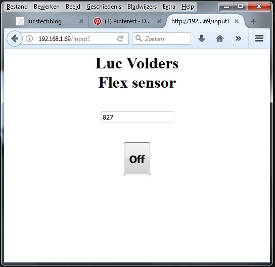
As you can see it is pretty straightforward.
I start with a timer that every 100 miliseconds calls a routine that reads the analog port and puts the result in the variable called value.
The main part has some fancy HTML code that makes sure everything looks great on the webpage and puts the variable in a textfield which is updated every time the test routine is called and that is every 100 miliseconds.


In stretched form the analog input reads a minimum value of 340


When bend to the max the value of the input is at maximum 900

The readings make perfect sense as they are the reverse of the multimeter readings. The ESP reads the voltage on its analog port and as the sensor is bended more the resistance is lower and therefore more voltage will be read which gives a higher value on the analog port.

All kinds off readings were seen by the in between steps. So the more the sensor is bend the higher the reading will be. This is exact the thing I was looking for.

Beware. The values of the measurements alter not only when bending the sensor but also when putting pressure on it. So make sure you do not touch the part of the sensor where the Velostat is when bending, but just bend it by the ends.

Pressure

As just stated the resistance not only alters by bending the Velostat but also by putting pressure on it.
So next to making a flex sensor I wanted to test it as a pressure sensor.


I started by cutting a piece of Velostat of 7 x 7 cm.


Just as with the flex sensor I put some Aluminum tape on both sides and glued it together with some painters tape.


Again make sure that the pieces aluminum tape on both sides do not touch eachother and touch only the Velostat.

Time for some testing.

I did some readings with my multimeter and measured a maximumj resistance of 1200 ohm in the normal condition and a minimum resistance of 20 ohm when I put an enormous pressure on the pad.

 
The Axell-Benz formula tells me to use a pull-down resistor of 220 Ohm to get the best readings on the ESP's analog port.

And indeed the readings were great.


About 190 in normal condition.


About 800 when under pressure.

So I had an idea.

Could I use this as a scale for measuring weights ???


I did some testing with various weights in a bowl. The results were indeed varying with the weight. However they were not consequent. When I moved the weight a bit on the presure pad the readings were differnt at the same weight. When I put a bowl with 400 gram sugar on the pad it sometimes would give me a reading of 616 and the next time 580. So the readings were not consequent with the same weight.
Therefore this is not usable as a scale.

However.


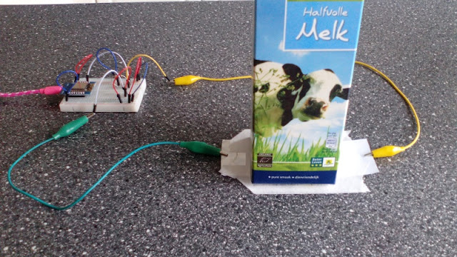
An empty pack of milk would give me a reading of 100 to 190.
When filled with 100 ML water I would get a reading of about 400.

This means that for pressure testing this works flawlessly.

Applications.

What is it good for.

Well I am not going to tell you that I made a sensor that I put in my fridge to tell me that I was running out of milk. That would be as stupid as the April fools joke that told me that the light of the fridge was actually out when I closed the door (and believe me people thought it was indeed a serious project).
Although I do know that some fridge maunufacturers are indeed experimenting with pressure pads that tell you that you are running out of eggs, milk etc etc etc.

So let's look at some real, practical solutions.
- A pressure pad can tell wether a water tank (be it for irrigation or whatever) is running low.
- A pressure pad put into your shoe can be made into a step counter


- A pressure pad can be positioned under a mat to detect a person entering a room
- A pressure pad can be put in the bottom of a bag/box detecting if it's being lifted
- A flex sensor put on your finger can control the movement of a servo for controlling a robot finger.
- A flex sensor on your finger could control the volume of an audio installatiuon
- A flex sensor on your finger could control an IR remote

Keep in mind that you can not solder the aluminum tape. So this is only usefull for testing purposes, or if your project is not that critical and you can use alligator clips. If you want a more permanent solution use copper tape. I bet it will be even more conductive and you can solder it for a permanent project.

That's it for now.
Have fun

Luc Volders

Friday, April 13, 2018

Raspberry Pi on-off switch

For a complete index of all my stories click this line

Lately I have been intensively being playing with my Raspberry Pi's. Indeed I have several Raspberry Pi-2's, Pi-3's and Zero's as well as Zero-W's. Many of them being put to use as an internet radio, domotics server, printer server, photo cam, control-system for my 3d printer etc. etc.

And the more I use them the more I miss an on-off button. So on my headless systems (systems without a monitor, keyboard and mouse) there is no easy way to shut-down the Pi. I have to SSH into the Raspberry and then use the shutdown command. Sometimes that is no problem however for my stand-alone internet radio that is annoying.

Beware that just pulling the power-plug from the Raspberry might corrupt your SD card, therefore that is no option.

So let's make an on-off button for the Raspberry.

The hardware

The hardware is very straightforward and identical for the Raspberry Pi 2, 3 and Zero.


Above is the breadboard layout for the Raspberry Pi 2 & 3


 And this is the layout for the Raspberry Pi Zero / Zero W


The Raspberry Pi-Zero has no I/O headers. So you could solder the wires direct to the board. However I urge you to solder headers and use Dupont wires to attach them to your breadboard. More projects with the Pi-Zero will follow and then a header will make it easier to experiment.
 

Just put a switch on a breadboard and attach one lead to GND and the other lead to GPIO3
That's all.

Switch ON

This is the easy part and achieved automatically.
As soon as you push the button the Raspberry will boot.
This is build-in in the Raspberry-Pi. As soon as GPIO-3 is momentarily connected to GND the Raspberry is triggered to switch on.

Switch OFF

This is a bit more complicated and involves some Python programming.
You could use the Geany program editor. However to keep things simple just open the nano editor with the name of the program we are going to write.


First open the terminal window and then make sure you are in the home directory by issuing the following command:

pi@raspberrypi:/ $ cd ~

and then type the next command to start the nano editor:

sudo nano onoff.py

Type in (or copy/paste) the next program lines.


#!/usr/bin/python3

import os
import sys
import RPi.GPIO as GPIO

GPIO.setmode(GPIO.BCM)
GPIO.setup(3, GPIO.IN, pull_up_down=GPIO.PUD_UP)

def onoff(switchno):
 os.system('sudo shutdown now') 
 
GPIO.add_event_detect(3, GPIO.FALLING, callback=onoff, bouncetime=300)

try:
 while True:
  pass
   
except KeyboardInterrupt:
 GPIO.cleanup()


When finished press CTRL-X and answer yes at the question wether the file needs to be saved and look if the right name (onoff.py) is being used.
   
Let's have a look at the program.

I started by importing the needed libraries. Without the RPi.GPIO library the I/O ports can not be used by Python. And the OS library is needed to shutdown the system.
The GPIO mode is set to BCM so we can call the I/O ports by name rather then by pin number. And then GPIO 3 (where the button is attached) is defined as an input with a Pull-Up resistor.

Next a function is defined that calls the os.system library to shutdown the Pi
And then an interrupt is defined that tests if the GPIO port is connected to GND (that is when the switch is pressed). If that happens the function is called that switches the PI off.

The last part just makes sure the program runs indefinitely.

Now there is just one last thing to do.

Make sure the Python program runs at booting.

As we are going to use our Pi for multiple purposes we need the Pi to be started up fully. Meaning the GUI needs to be running before our program starts. We can do that by altering the file autostart in the /home/pi/.config/lxsession/LXDE-pi/ directory.
So in the terminal window type:

sudo nano /home/pi/.config/lxsession/LXDE-pi/autostart

and alter the file by adding the line @python3 /home/pi/onoff.py &

Enter this line before the line that starts the xscreensaver otherwise it might have problems with autorunning. My autostart file looks like this:

@lxpanel --profile LXDE-pi
@pcmanfm --desktop --profile LXDE-pi
@python3 /home/pi/onoff.py &
@xscreensaver -no-splash
@point-rpi


The & at the end of the line makes sure the Python program runs in the background and does not open a terminal window. So you will start with a clean desktop.

How to use the on/off button

Reboot your Raspberry and the program will be activated.
If you press the button the Raspberry will shut down. Pressing the button again makes the Raspberry start-up again.
No keyboard, mouse or screen needed to accomplish this anymore.

This uses some of the Pi's resources and therefore will slow down the Pi. This is most noticeable on a Pi Zero.
Using this as a stand-alone program therefore is overkill. I will be incorporating this method however in several projects (stand-alone internet radio, PI-camera, Pi-security camera etc) which makes it very usefull.

So keep returning to these pages for more projects. 

Till next time: have fun.

Luc Volders

Friday, April 6, 2018

RGB-Strip Control over Wifi Part 2

This story is a sequel to earlier stories on this weblog. I advise you to read them first for some basic understanding on how this all came together.

First important story was about controlling a ledstrip. This story showed how to use power transistors to set the colors of a ledstrip.

The second story was based on the first story however in this story the ledstrip was controlled by an Android phone over bluetooth.

In the third important story in this sequel I introduced you ESP-Basic. A full blown Basic language for the ESP-8266 which makes all kinds of projects with Wifi incredibly easy. Read that story here: https://lucstechblog.blogspot.nl/2017/03/back-to-basic-basic-language-on-esp8266.html

The fourth story showed how easy it is to use sliders in ESP-Basic to control the colors of a neo-pixel strip.

And in this installment I am going to combine all previous techniques to control a full-blown ledstrip over Wifi using power transistors attached to an ESP-8266 and programmed in just a few lines of Basic.

So the objective is to attach a full-blown ledstrip to an ESP-8266 and control it over Wifi. Why should you do this instead of the previous version with bluetooth.
In the first place wifi has a bigger range as bluetooth so there is more ease of use. And secondly: you can do it from anywhere in the world. So you can set the colours of the ledstrip in the color of your choosing before you get home. Or you can use it even to notify people that you are on your way home.

Let's start.

The theory.

A ledstrip can produce thousands of colors when it is controlled in the right way. In the Bluetooth variation described in the previous stories I used several predifined colors. However I wanted more freedom.

So the leds had to be controlled by an analog signal. A digital signal just sets the led ON or OFF. An analog signal is able to control the intensity of the light.

Now I am using the ESP-8266 (NodeMCU or Wemos D1 mini version) and the ESP has no analog output capabilities. That is the same on an Arduino. So clever programmers have simulated an analog output by something called PWM (Pulse Width modulation).
Basically it works by setting the I/O pin in a high and then low state but in a very fast pace. By doing so the pin is pulsating. And if you do that fast enough you can dim the LED in steps.
Sounds complicated ??? Well it is. But we can use this by a very simple command.

Let's try it first with a simple led.


Build the breadboard like the picture shows you and program your ESP with the following Basic code:


 timer 500, [set]  
 slider pwmval, 0, 1024  
 wprint "<br/><br/>"  
 button "<h2>Off</h2>", [Off]  
 wprint "<br/>"  
 wait  
 [set]  
 io(pwo, d5, pwmval)  
 wait  
 [Off]  
 io(po, d5, 0)  
 end  


This simple program puts a slider on your screen and an OFF button.
By moving the slider the led will be dimmer or brighter. Just what we need to control all the colors of the ledstrip.

As this works we have the fundament working. We can now expand it to a full RGB strip control.

Hardware


Look at the breadboard. As you can see, just like in the blue-tooth ledstrip control, we are going to control the ledstrip with TIP120 transistors.

The Tip120 transistors can supply each a maximum current of 5 amperes.
5 Amperes is 5000 Mili Amperes. Each led of the RGB strip will consume 20 Ma.
So in theory each Tip120 can control 5000/20 = 250 leds in the strip. You will need to put cooling fins on the TIP's for this. But my advise is to not drive them to the max.

My ledstrip is 5 meter long and has 150 leds of each color (150 Red, 150 green and 150 Blue). So the Tip120's should supply enough current to control the complete ledstrip.

Just make shure that your power supply has the same specifications. It has to be a 12volt power supply that supplies enough current for the complete ledstrip.
So what I did was to look at the original power supply that was issued with my RGB strip. It was 12 volts at 2 amps. So not enough to supply the full strip !!!

Make sure that the 12Volt power is only attached at the TIP120 side. The NodeMCU needs its own 5 volt power supply.

I attached 3 TIP120 transistors with resistors to d5, d6 and d7 of the NodeMCU.
The schematics are straightforward and will give you enough information to build this yourself

Basic program

The Basic program is just an extension of the small program listed above. I made 3 sliders 1 for each color (R, G and B) and on button to put the ledstrip off.


 timer 500,[set]  
   
 wprint |<h1 style="text-align:center;">Luc Volders</br>RGB-STRIP</br>CONTROL|  
 wprint "<br/><br/>"  
   
 slider r, 0, 1023  
 cssid htmlid(),"background-color: red"  
 textbox r  
 wprint "<br/><br/>"  
   
 slider g, 0, 1023  
 cssid htmlid(),"background-color: green"  
 textbox g  
 wprint "<br/><br/>"  
   
 slider b, 0, 1023  
 cssid htmlid(),"background-color: blue"  
 textbox b  
 wprint "<br/><br/>"  
   
 button "<h2>Off</h2>", [Off]  
 wprint "<br/>"  
 wait  
   
 [set]  
 io(pwo,d5,r)  
 io(pwo,d6,g)  
 io(pwo,d7,b)  
 wait  
   
 [Off]  
 r = 0  
 g = 0  
 b = 0  
 io(pwo,d5,0)  
 io(pwo,d6,0)  
 io(pwo,d7,0)  
 end  


Actually the Basic program is an alteration of the Basic program I introduced in the previous story in this line-up where we controlled a strip of Neopixels. Read that story by clicking here.

The alterations are that the RGB strip will react instantly at any alteration of the sliders. And the Neopixel command has been aleterd in these commands:

io(pwo,d5,r)
io(pwo,d6,g)
io(pwo,d7,b)

These commands will set the I/O pin in a PWM state defined by the r, g or b variable.

So there it is:  a complete Wifi controlled RGB strip in just 38 lines of code !!!


The pictures above show you how it functions in real life.
As you can see there are textboxes below the sliders. In these text-boxes you can fill in any figure you like (between 0 and 1024) for test purposes or for fine-tuning the slider setting.

The ESP8266 is really a marvel and ESP-Basic is fantastic !!

Till next time
Have fun

Luc Volders

Sunday, April 1, 2018

ESP-Basic Degree

I think many of you wonder where I got all the knowledge for writing all the stories on my blog.
And why I am using ESP-Basic so much.

Well the answer is simple.
I studied ESP-Basic at the Thunderwood College. And to be specific ESP-Basic for IOT.

It took me months and now at last I am picking the fruits of my efforts: I received my batchelor degree !!!


I am proud to show it to you so here it is !!!
You can send congratulations to my e-mail adress.

If any of you is interested in getting the same degree or a degree in other parts of science please visit the Thunderwood college: http://thunderwoodcollege.com/

They offer degrees in allmost all lines of science/art/biology/economics etc.
The information on their site is totally free however you are politely asked to do a donation if you want to join their association (very reasonable suggestions) or get a degree.

It cost a lot of time but however was a lot of fun.

Till next time
Have fun

Luc Volders


Oh and please look at the date of publishing !!!!